Bridge structures are susceptible to a range of rigorous conditions. These include: repeated exposure to heavy loads traveling at relatively low speeds, potentially damaging weather elements, daily thermal cycles, and the occasional seismic event. These conditions require bridge bearing designs which can withstand a wide range of factors without compromising the integrity of the structure.
The ultimate responsibility of the bridge bearing is to allow for the controlled transfer of loads and the energy of movements from the bridge deck to the underlying bridge structures. While there are several general bearing designs available for these purposes, many highway bridges, which must accommodate large amounts of consistent traffic, benefit significantly from the inclusion of PTFE (polytetrafluoroethylene) slide bearings as opposed to those such as roller bearings.
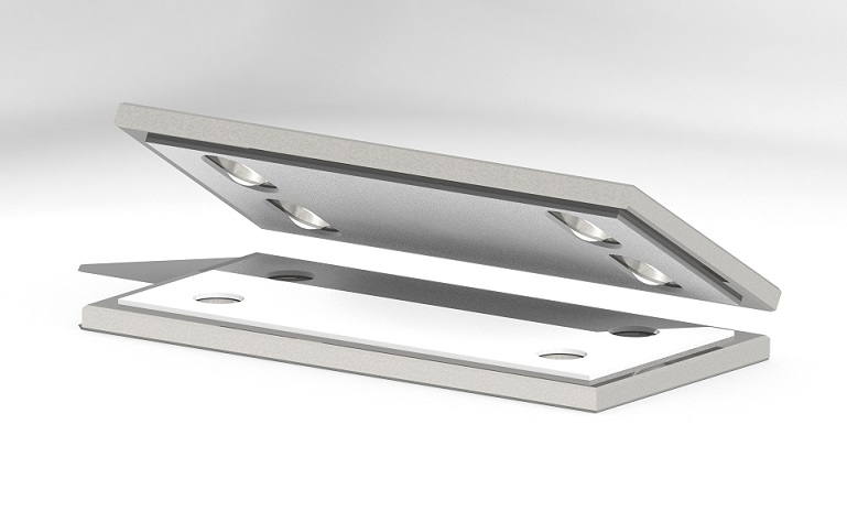
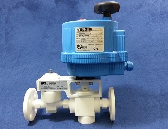
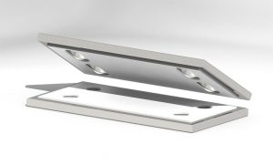 PTFE on Stainless Steel Slip Style Bearing
One of the most noticeable benefits of PTFE slide bearings in bridge design is the low frictional resistance it offers. PTFE is known for its remarkably low coefficient of friction [F=μN], and when combined with self-lubricating qualities, it becomes quite efficient at resisting those noted rigorous conditions.
Coefficient of Friction in Relation to PTFE
Friction is essentially the ratio of resistance between two objects that come in contact with each other. The measurement of this friction, the coefficient of friction (COH), shows the relationship between the two objects. Mathematically one can determine this relationship by applying the following formula:
F=μN
Where
F = frictional force
μ = coefficient of friction
N = normal force
These measurements can vary among same materials when comparing static friction to kinetic friction. When the coefficient is close to a value of zero (0), the friction is minimal. Such is the case with typical PTFE slide bearings. In fact, in terms of the broad availability of various engineering materials, PTFE offers the lowest coefficient of friction at an estimated COH of 0.04 for both kinetic and static friction, compared to a lubricated steel at 0.05 (kinetic) or 0.1 (static).
Slide bearing designs with PTFE are commonly used with stainless steel plates, and the PTFE is applied in one of two methods.
- The PFTE is applied between two flat stainless steel plates at a surface area smaller than that of the steel plates to avoid creep.
- The PTFE is applied to curved stainless steel surfaces to accommodate larger rotations (beyond 5 degrees).
Primary Benefits of PTFE in Bearing Design
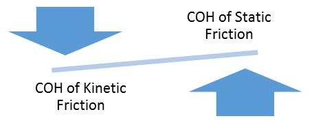
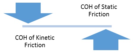
Due to the low coefficient of friction, PTFE offers a significant benefit in bridge bearing design. In what is known as stick-slip action, two objects typically alternate between freely sliding against each other and abruptly sticking to each other. Usually this is the result of a difference in the coefficient of static friction when compared to the coefficient of kinetic friction, as demonstrated in Graphic A. The imbalance between the two causes a jarring effect.
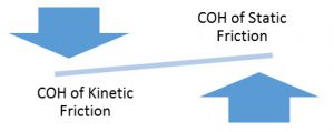 Graphic A – Slip-Stick Action as the Result of Differences in COH
However, as previously stated, PTFE is unique in that the COH is minimally different (at typically 0.01 or less) between these two friction forces. In materials that have a greater range of COH between static friction and kinetic friction, more force is required to overcome the resistance, which results in that stick-slip motion. Thus, a significant benefit of PTFE slide bearings is the relative absence of slip-stick action, as shown in Graphic B.
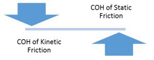 Graphic B – Absence of Slip-Stick Action in PTFE Bearings
Furthermore, slip-stick action usually increases in correlation with COH increasing when the mating surfaces of the bearing become contaminated with debris. In applications of PTFE, however, the COH remains largely unchanged when the jointing between the steel plates becomes exposed to contaminants.
Additional Benefits of PTFE in Bearing Design
In addition to the benefits noted regarding resistance of slip-stick action, there are other advantages to choosing PTFE in bridge bearing design. PTFE bearings:
- Require little to no maintenance. There are no repeated maintenance cycles required once installed.
- Can handle temperature extremes, both ambient and friction generated, stable between -80ᵒF and 400ᵒF (although design must account for thermal expansion).
- Are largely unaffected by chemicals. Over time the bearings will not diminish in integrity due to exposure to various acids and solvents which may come in contact with the bearings.
- Are highly impervious to small particle invasion. Other bearing designs are susceptible to damage or increases in COH in these situations.
- Prove to be highly resistant to influences of weather extremes.
- Offer vibration damping to the bridge structure.
- Are less bulky than other mechanical bridge bear designs.
Low COH – The Most Significant Offering of PTFE
One of the most crucial considerations which needs to be made in bridge bearing design is that of the coefficient of friction. PTFE slide bearings are unique in their ability to offer extremely low COH in regards to both the kinetic and static friction levels, thus significantly reducing any stick-slip effect. As more and more bridge designs incorporate steel structures, the additional benefits of PTFE slide bearings become more clearly visible and worthwhile, especially over time.
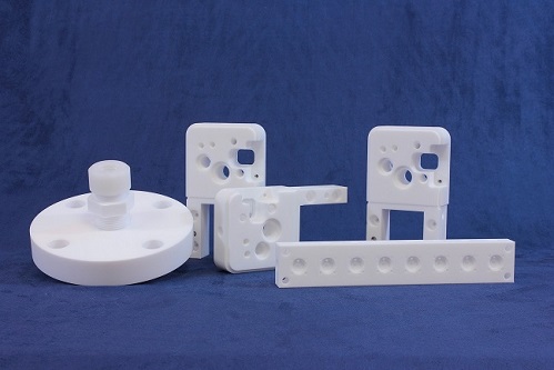
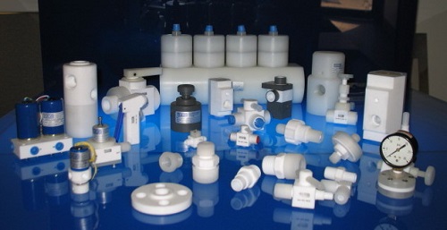
International Polymer Solutions Inc. (“iPolymer”) machines fabricates a wide range of PTFE products for the global market. iPolymer utilizes the unique fluorine-enhanced properties of fluoropolymers like PTFE, PVDF, PFA and PEEK to develop solutions which challenge industry. Visit us at www.ipolymer.com